Last year I discovered Robert Skinner’s YouTube channel. It’s one of those channels that should be much more followed. Robert has really cool and original ideas, shows every problem he encounters, how he resolves them, has great video editing skills and a totally chill tone. In September 2025, he released a video about a “kinetic lamp”. I jumped into it, as with every one of his videos, not knowing that before the end of it, I was sure I was going to try to reproduce it. But I had some ideas to try to improve it along the way. Robert started this project as a one-day build and finally finished a few days later. Spoiler: it took me 4 months. But that’s my excuse. I tried to improve it…
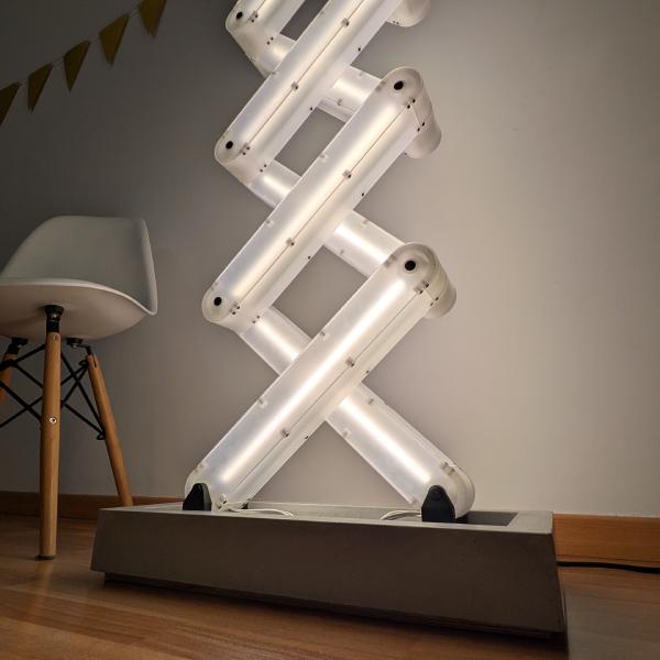
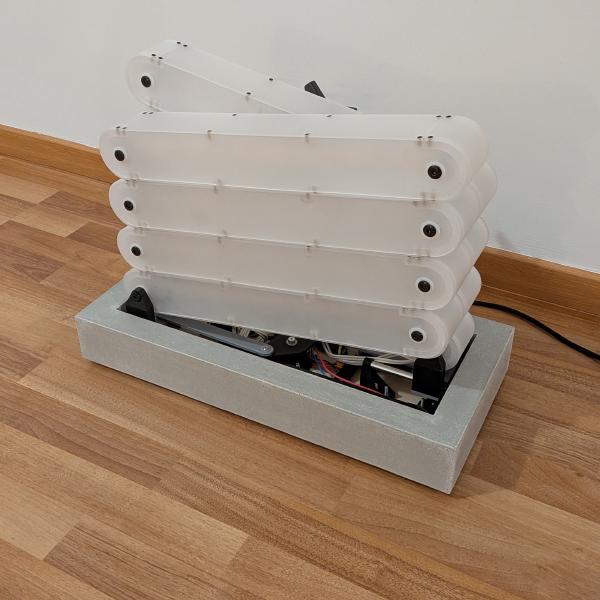
I have a thing with lamps. This one is the third I’ve built. My last 3 DIY projects were lamps. But this one feels special. Not only does the brushed acrylic diffuse light like nothing else, but let’s see some of the things inside. It also has the scissor mechanism which I find fascinating, directly coupled with the intensity of the lamp. It ticks all the boxes for me.
I started watching the video 3 or 4 times in a row. Each step felt doable, but it took time to wrap it entirely in my head. “You don’t need to know all the steps to finish it, just what the next step is” as they say.
CAD / Prototype
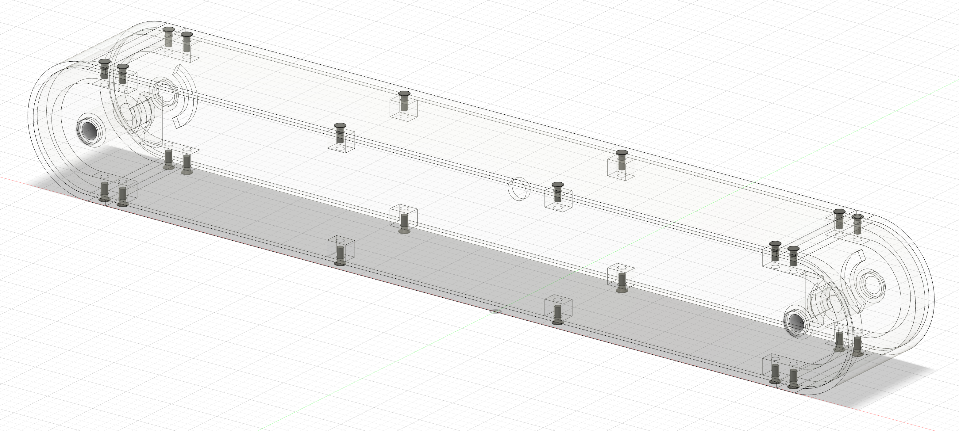
So it started with a bit of excitement, diving into an awesome project, and starting being obsessed by it. The first step for me was drawing a segment of this lamp in a CAD software. I came up with my own measurements (a segment is 45×6cm), and 3mm acrylic thickness.
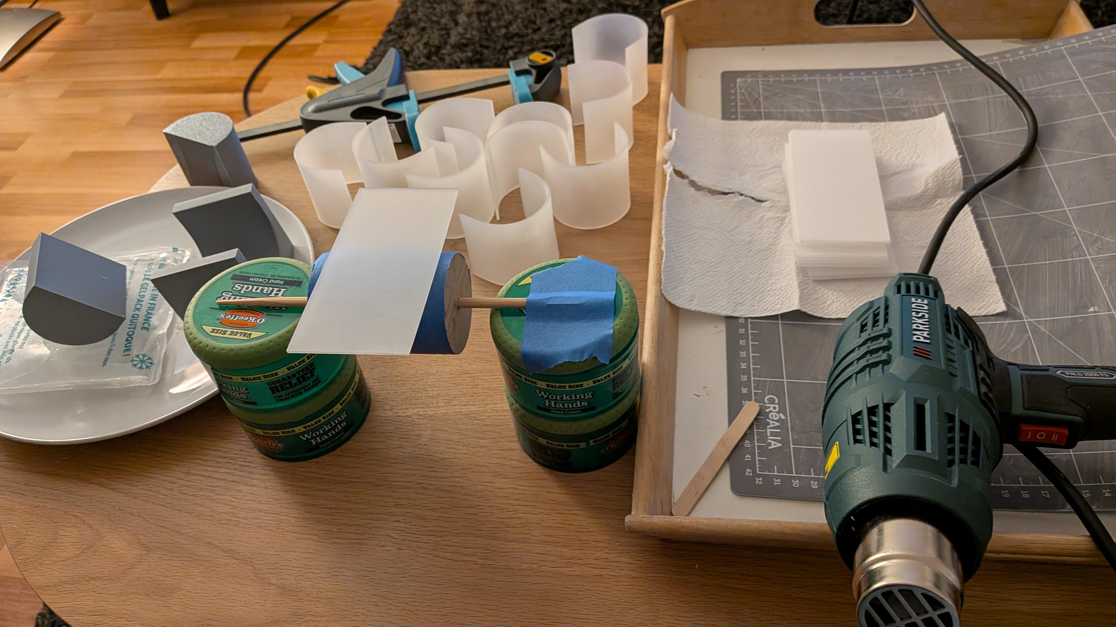
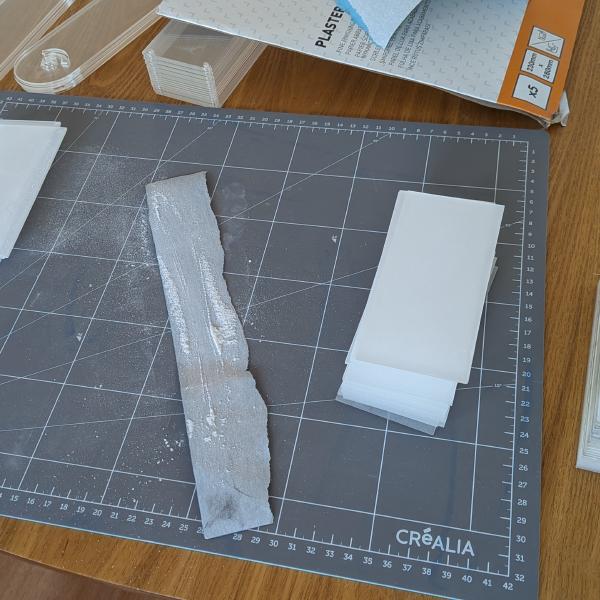
I looked for some online providers. In France there are some obvious platforms with great SEO for laser cutting on PMMA, but their prices are exorbitant. I found a small business to order only the pieces for one segment, to check if everything was good in the naive hope of using this first one in the final build. My main interrogation was the bending of the end cap. As I do not have a laser cutter, cutting a wood mold at the exact diameter was not possible as in the video. I ordered 6 pieces to try to have 2 usable bent ones. Luckily, I had a 50mm hole saw, allowing me to create a wood cylinder for heating the piece, and then press it into a 3D printed mold at the exact size. It worked great, but as I feared, the heat of the acrylic had deformed the mold. So, for the other pieces, I will print 2 molds to use them alternately, and a frozen bottle to cool them down between uses.
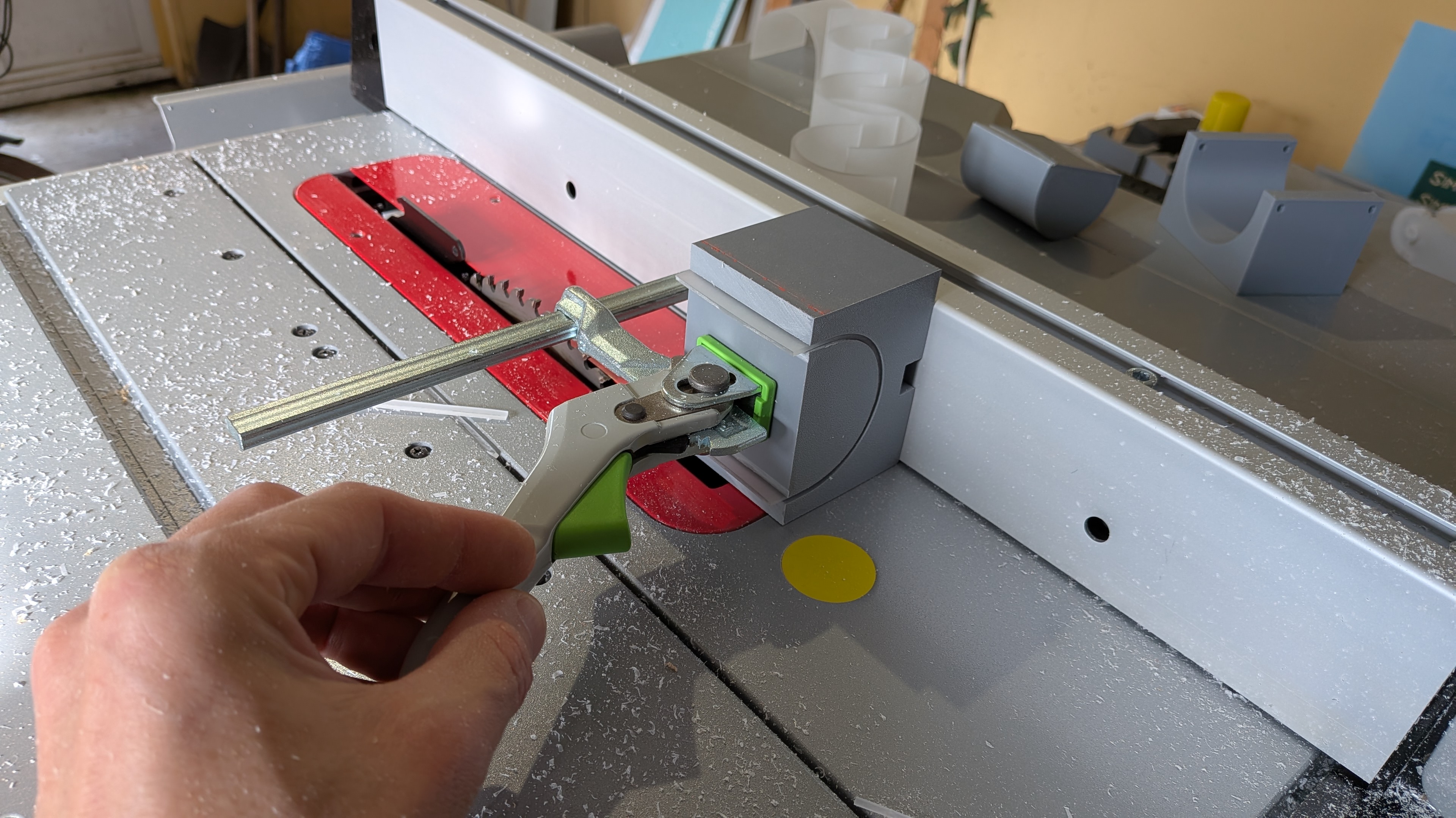
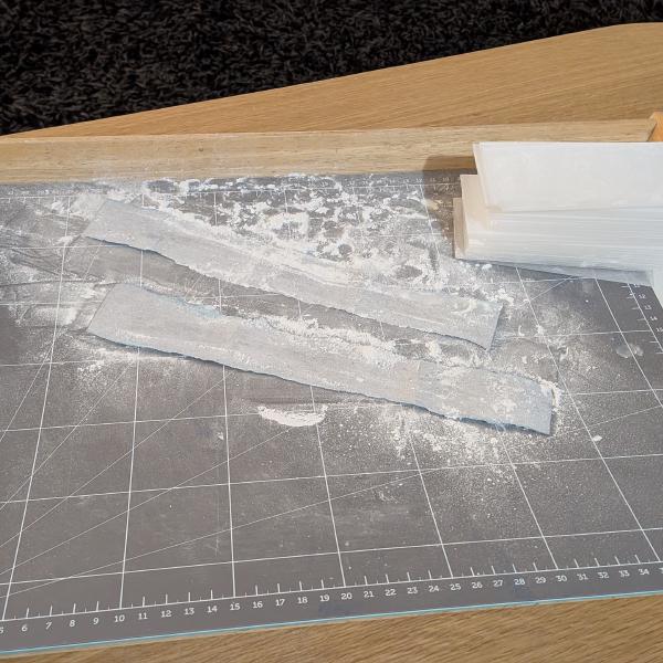
After bending the end cap, I cut them to the correct size, once again with a 3D printed jig, on my tracksaw.
The prototype ended great.
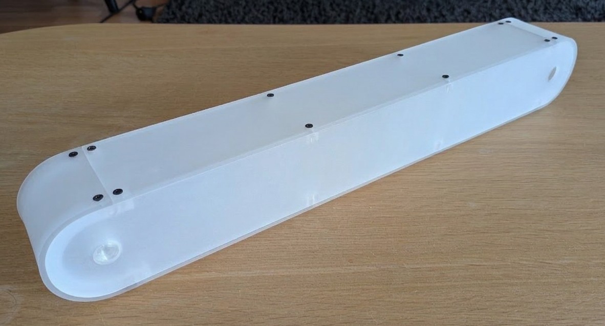
The only problem was weight, more than 400g. This thing was empty, no light, no bolts, and many other things I had no idea about yet but was suspecting. So back to the CAD software, I changed the thickness to 2mm. This is where I learned about parametric modeling. A bit late, so I restarted my design from scratch.
After many modifications, hesitations, and problem solving, I had a new drawing that fixed various problems I was discovering.

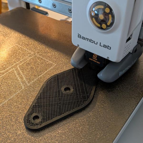
I’ll let you try to figure out why there are wavy lines on the pivot holes.
Building the segments
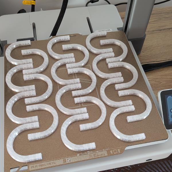
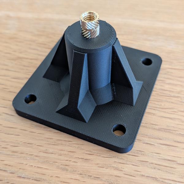
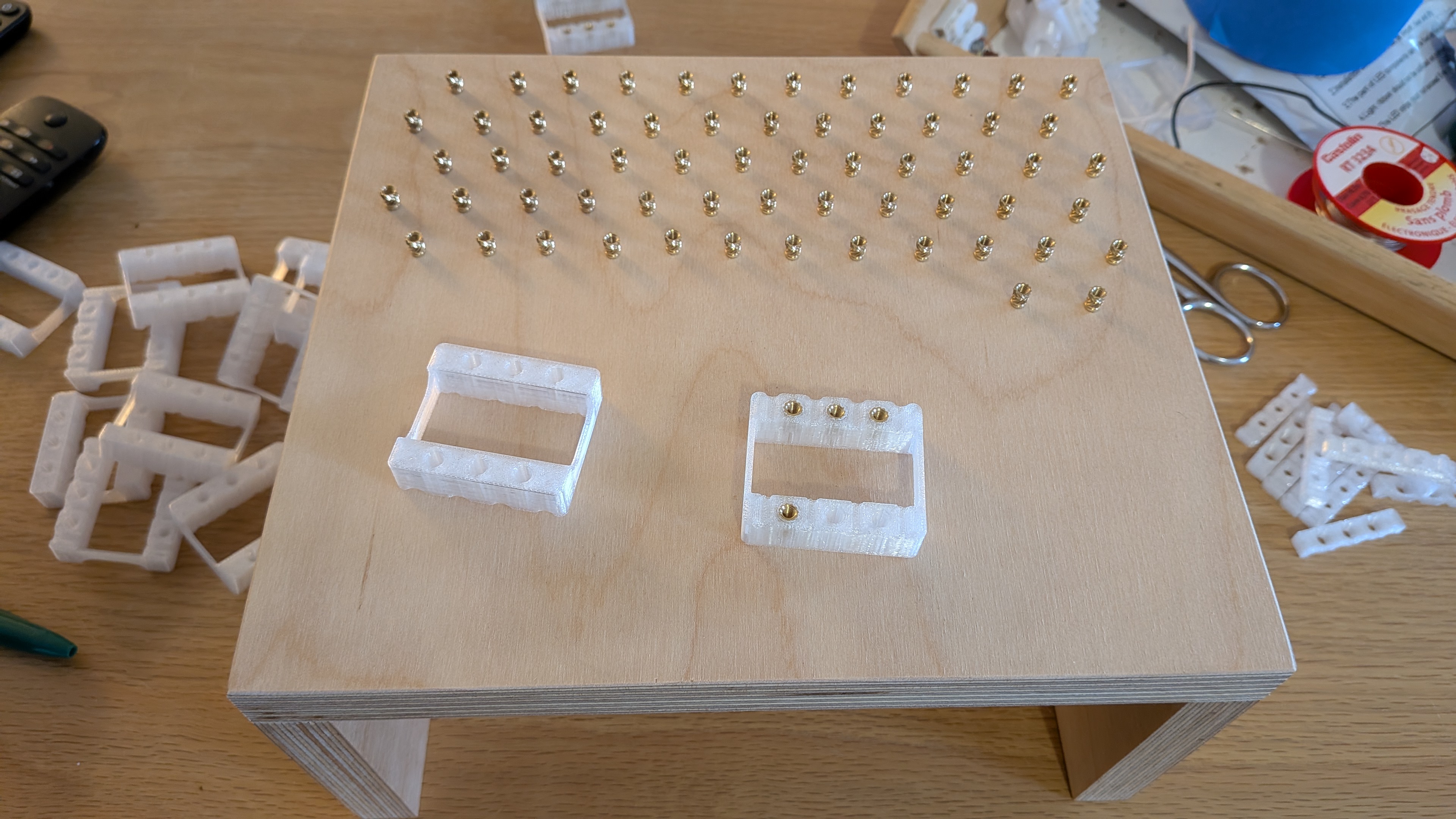
While waiting for my acrylic order, I started printing parts to assemble the segments.
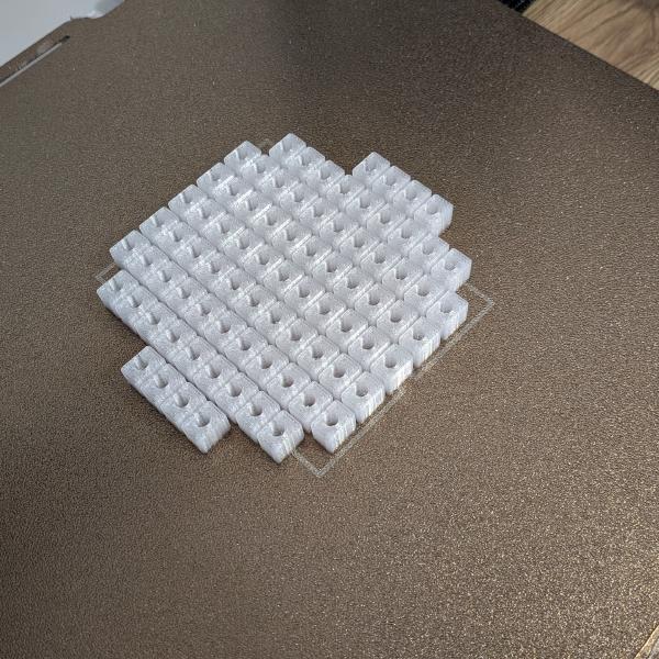
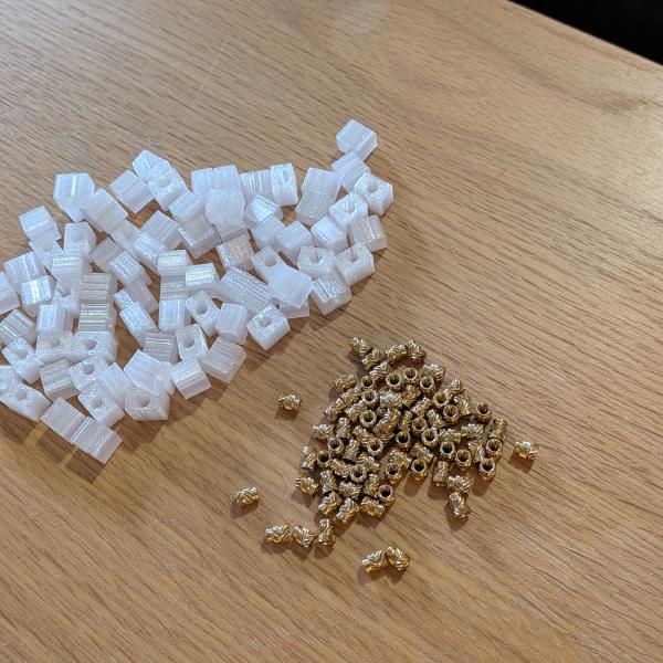
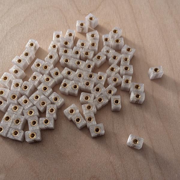
Yes, that’s a lot of threaded inserts. You can screw directly into the 3D print but it will not handle multiple assemblies very well. I wanted to be able to mount/unmount the segments multiple times, knowing the back and forth that awaited me, without damaging the threads.
Waiting for the acrylic pieces
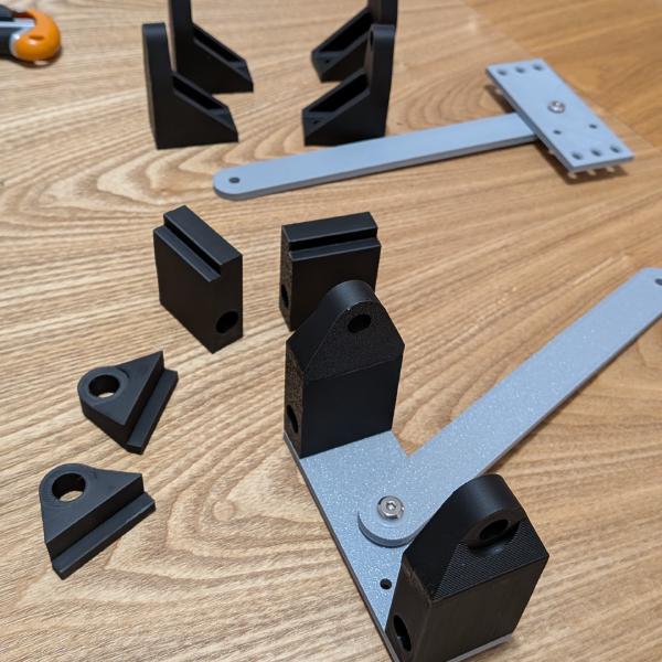
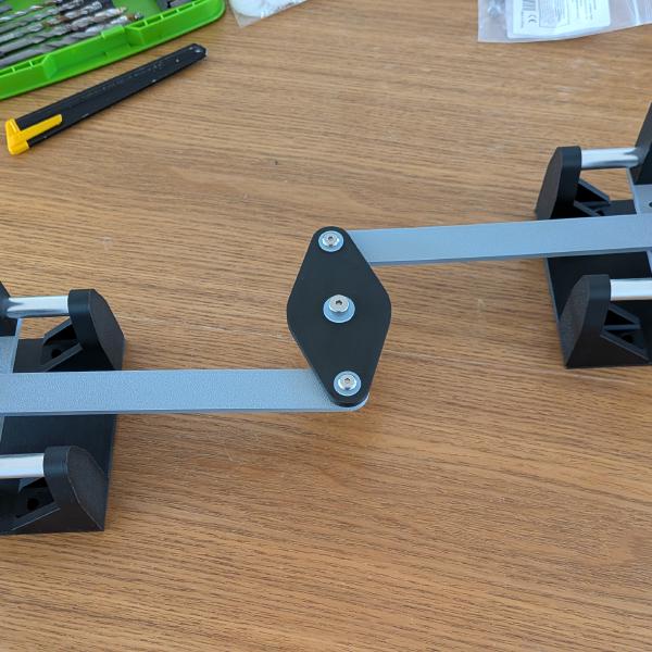
Then I started to think about the base mechanism and my first improvement. On his version, Robert fixed one end of the lamp on the base with a pivot, the other on a slider to allow the movement. But the side effect is that when deployed or folded, the lamp is not centered on the base. Not a huge deal but setting 2 sliders will allow me to keep it centered. The problem is: how to center it without having the lamp slide from right to left on the sliders? I thought about wire pulleys, rack and pinion, but with my limited CAD skills, a central pivot with one arm on each slider will do the job. So I learned joints, to animate the lamp.
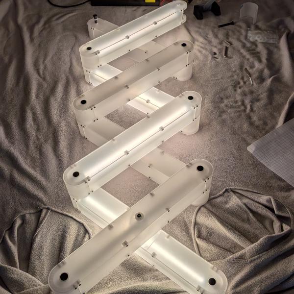
Finally, my order arrived. Clear acrylic, beautifully transparent, meaning one thing: lots of sanding.
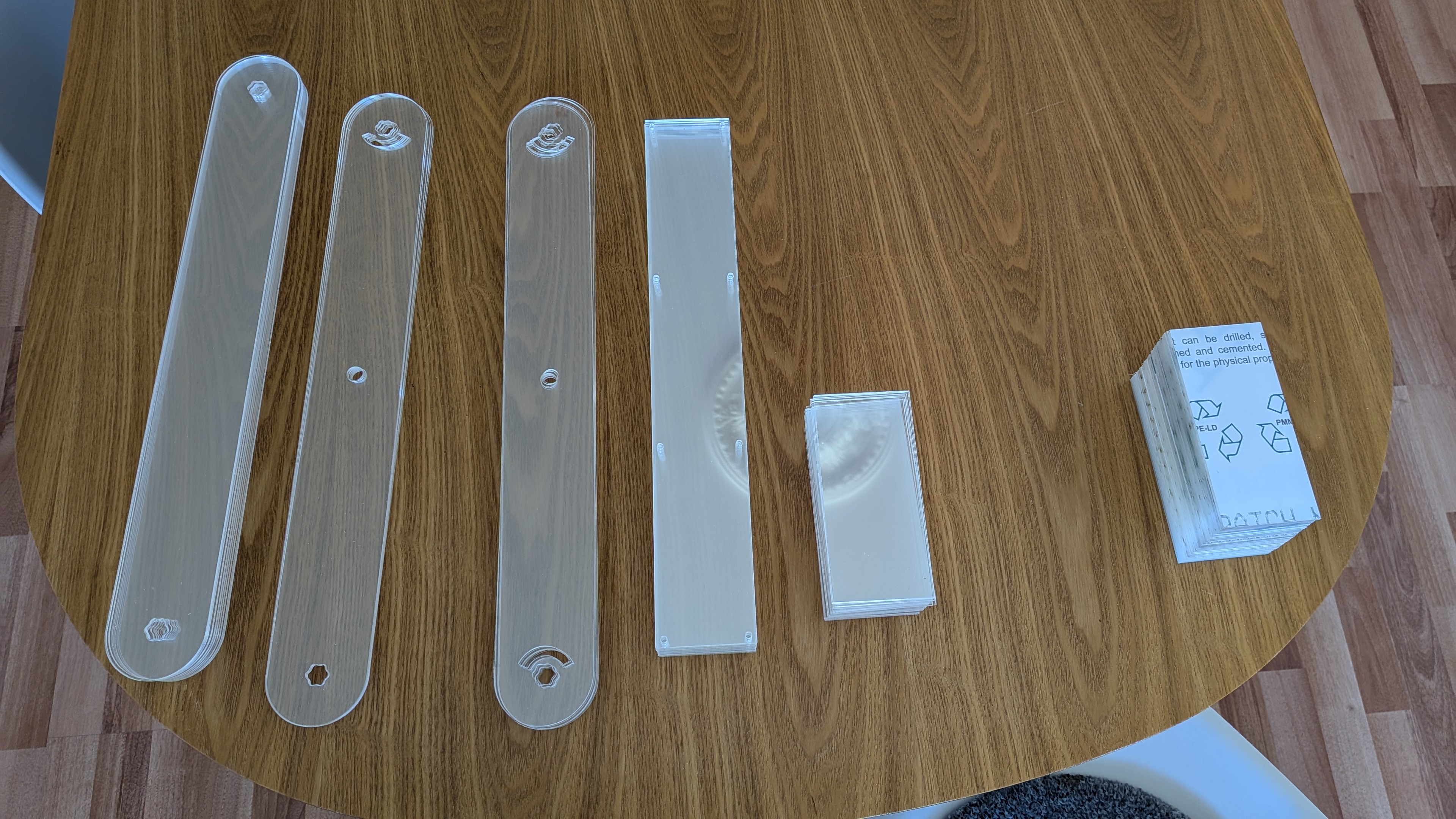
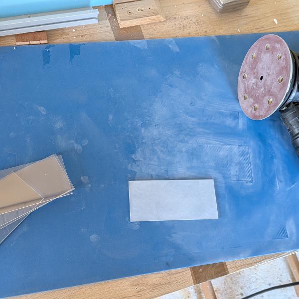
After cleaning the pieces, it was time to start glueing the blocks. I had never used epoxy, and, after trying on one little piece, I decided that it was not going to be today. It was too slow and messy for what I needed. I preferred to use CA glue. On the sanded acrylic it holds great. I needed a perfect alignment so I printed some jigs for both the small blocks and the curved end.
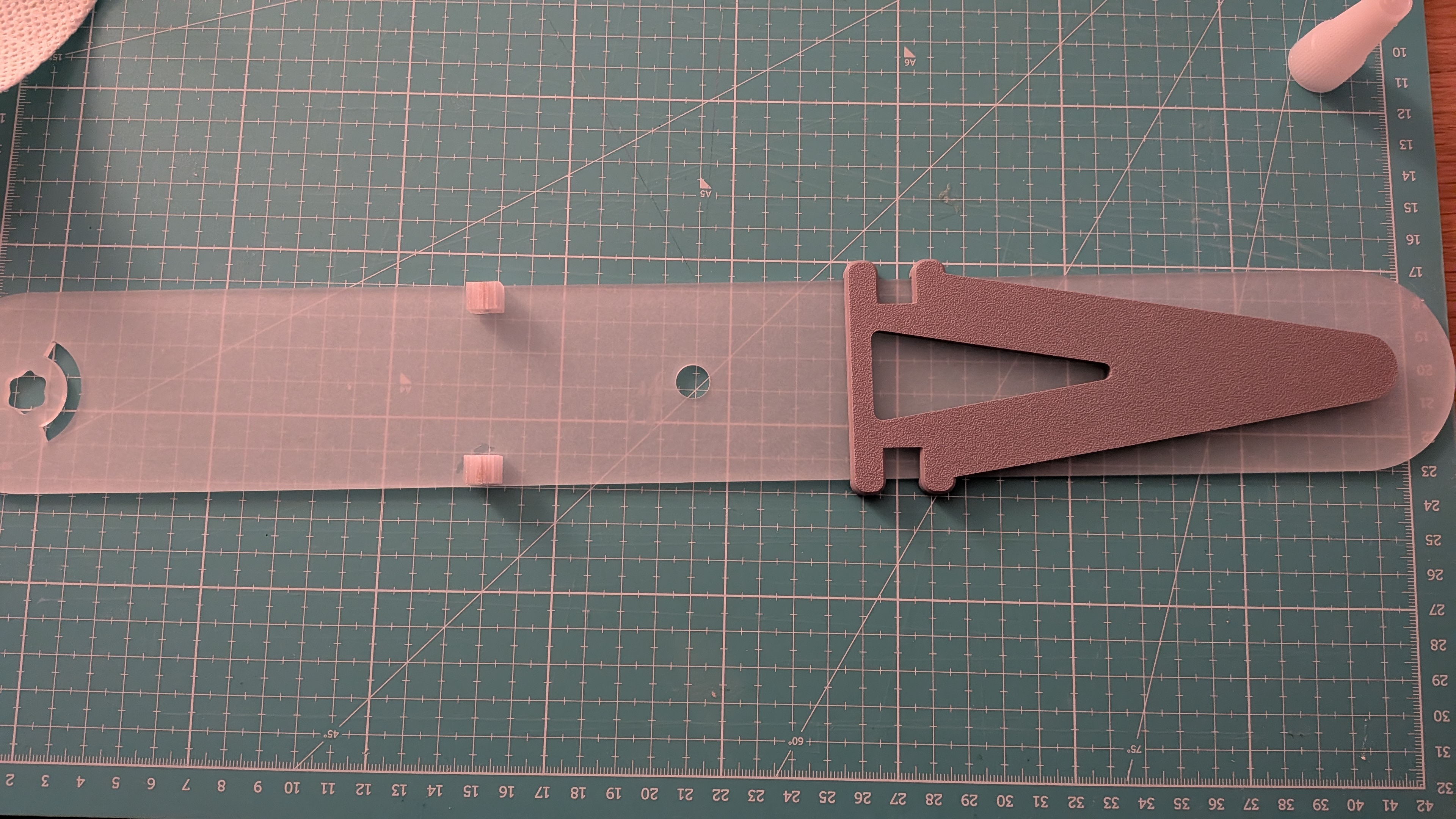
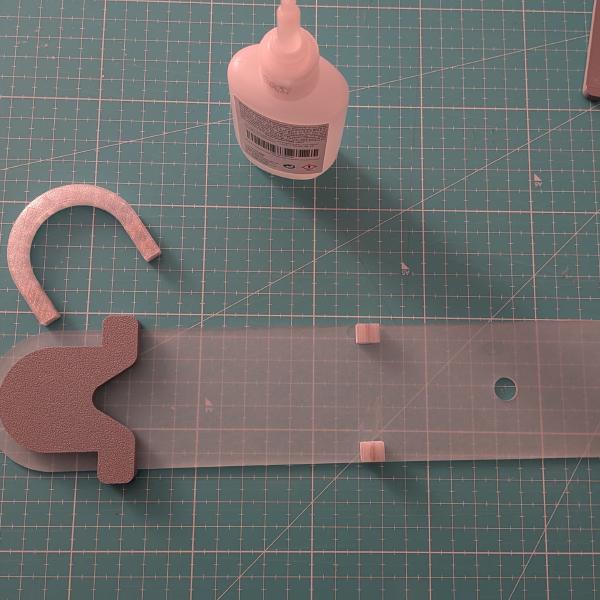
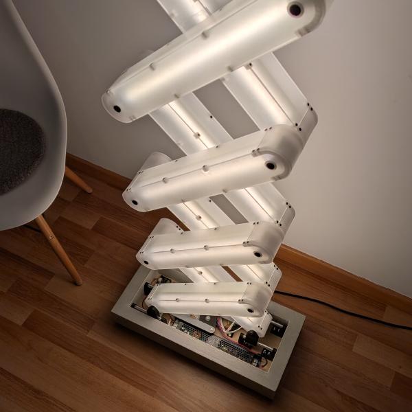
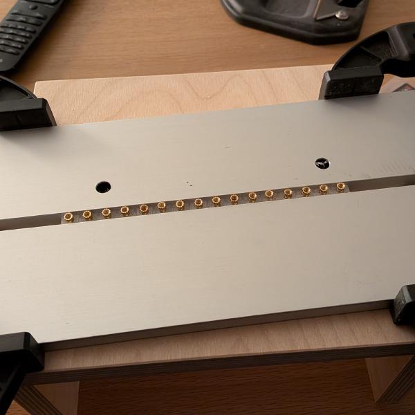
Then, comes another of my improvements. I wanted the segment to have 2 LED strips each, one on the front, one on the back. Thanks to that, while laid against a wall, the light will also be bouncing from the back for a softer light. I chose to set the connectors into the round part, outside of the usable space, to allow the maximum amount of LED strip between the two axes. Actually I picked the dimensions of the segment based on the LED strip cuttable segment.
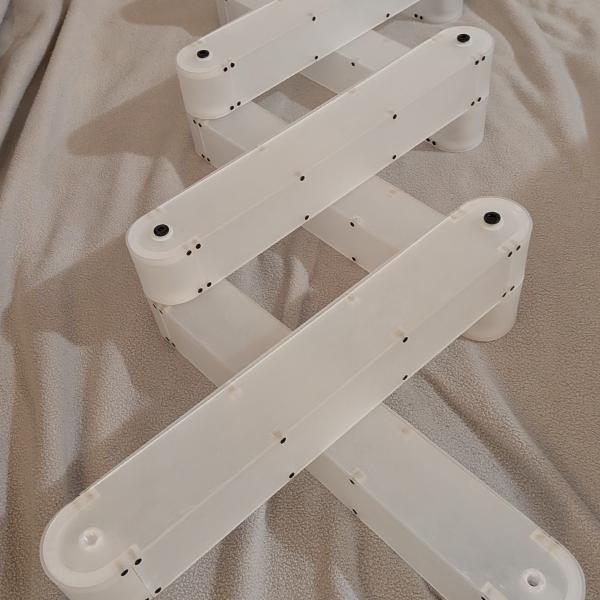
Now, the assembly began.
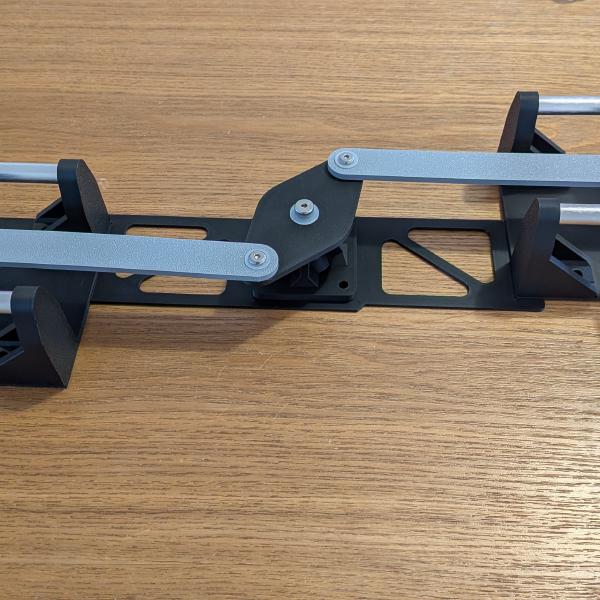
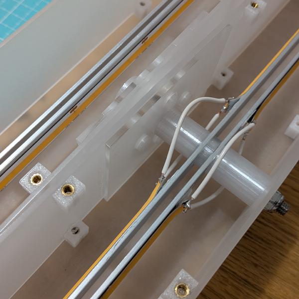
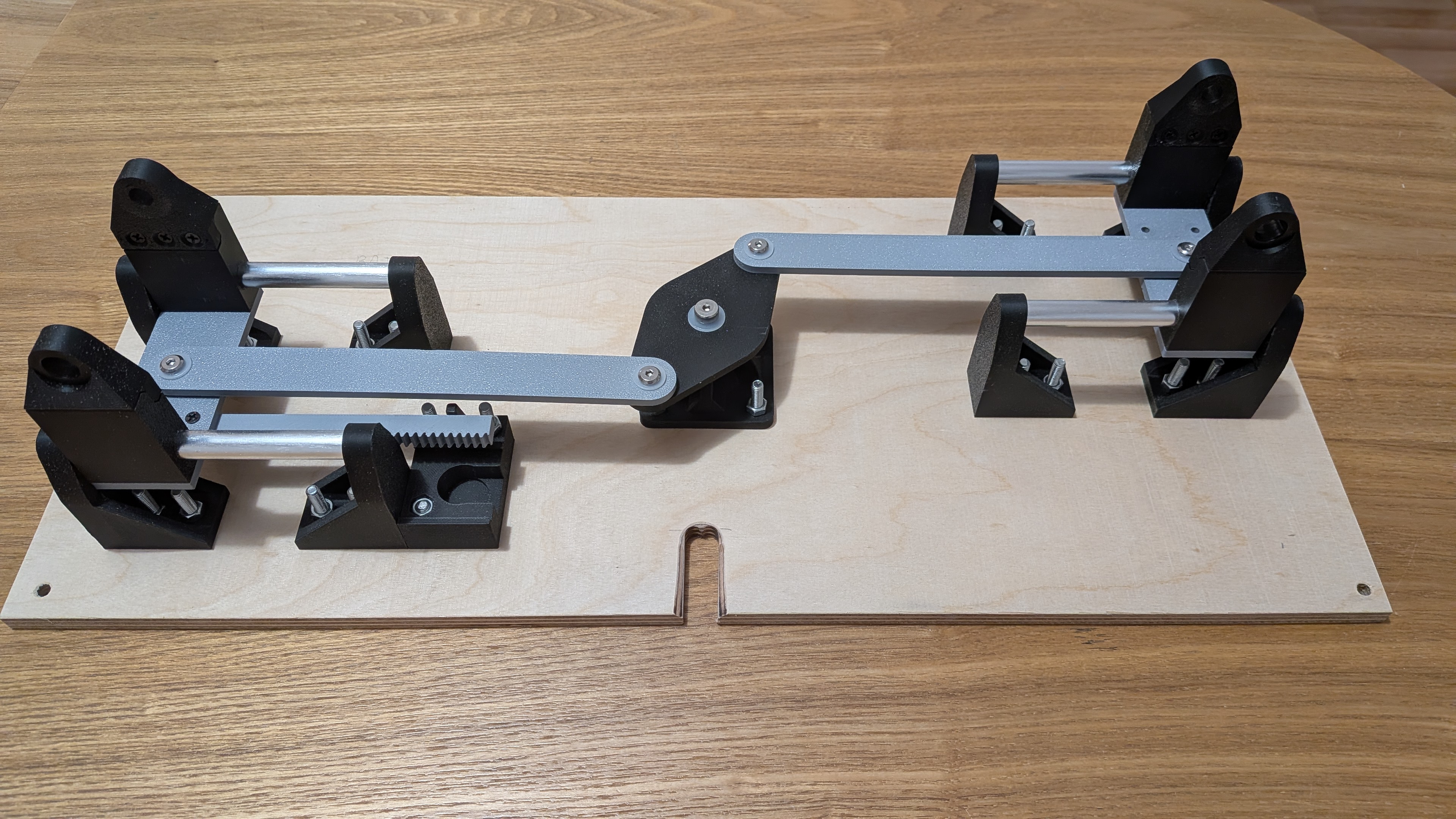
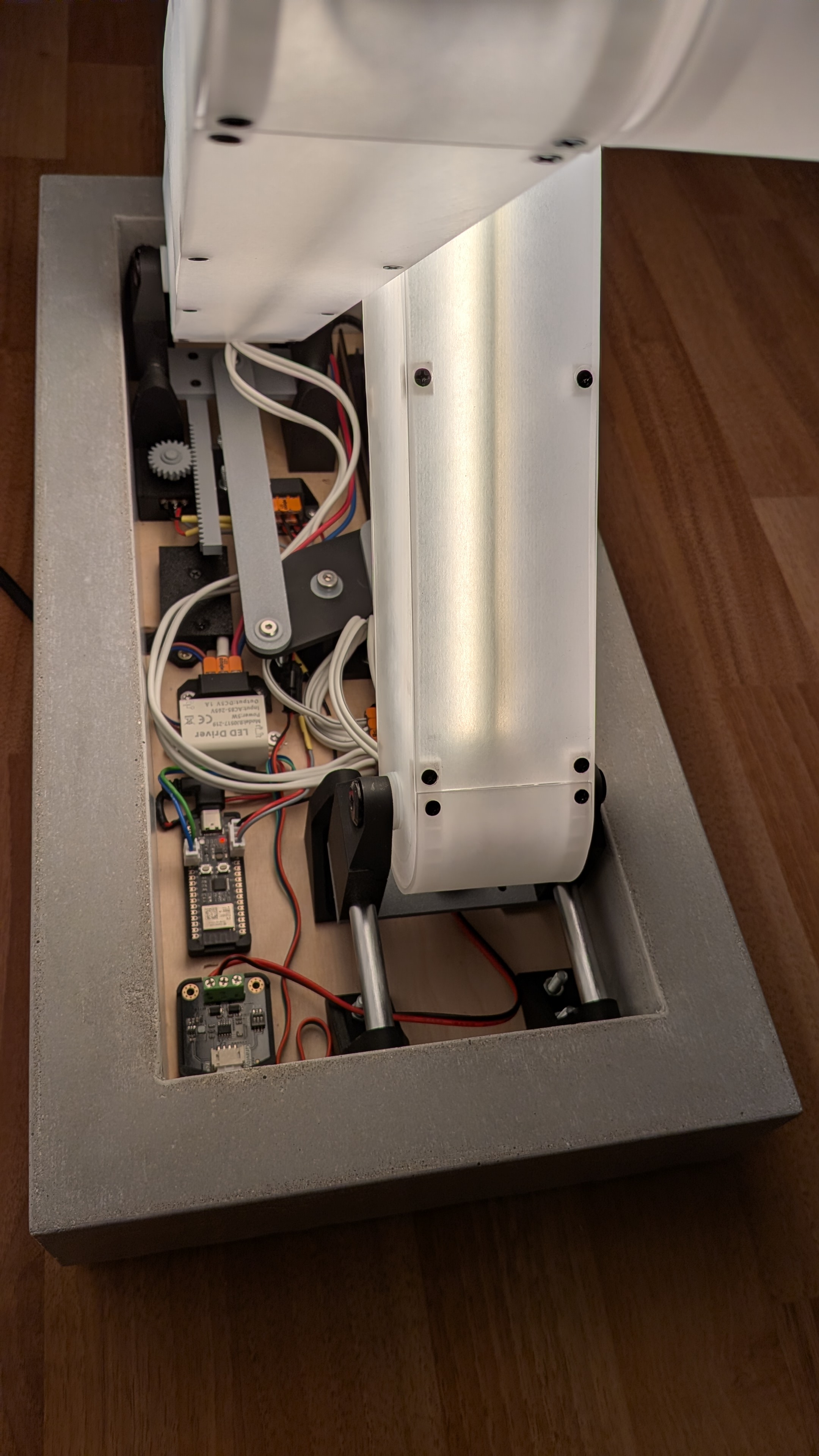
Base mechanism
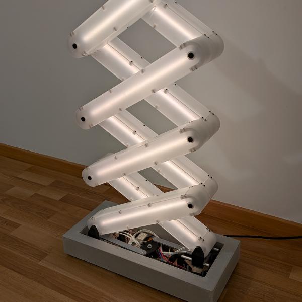
Now, it’s time for the base mechanism. As seen in the previous video, each one is composed of two 10mm aluminium tubes, held by 3D-printed parts. They are synchronized by the 2 arms mounted on a central pivot. I kept it as simple as my first CAD draft.
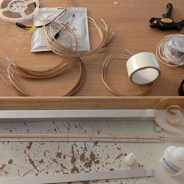
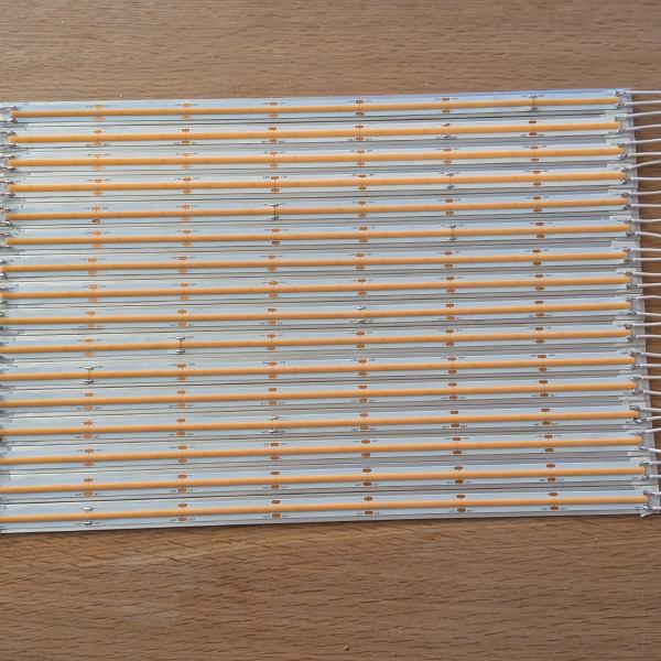
The electronics
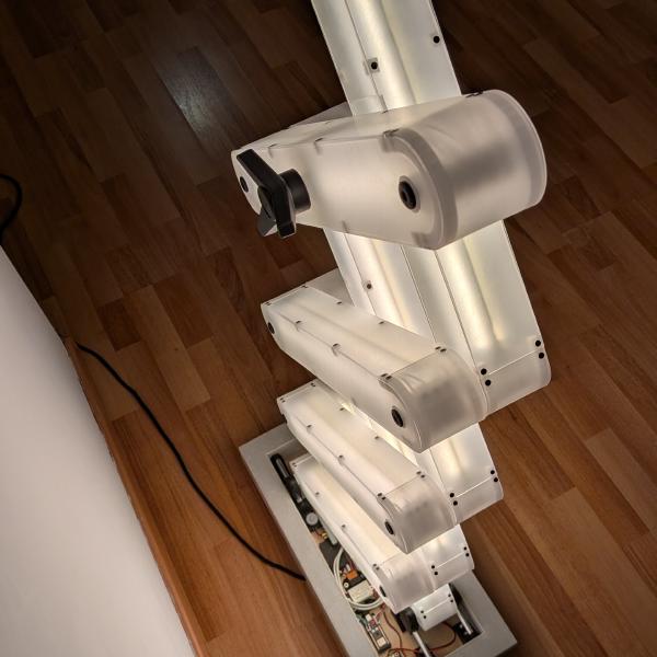
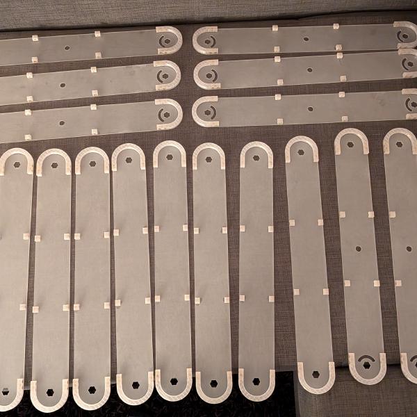
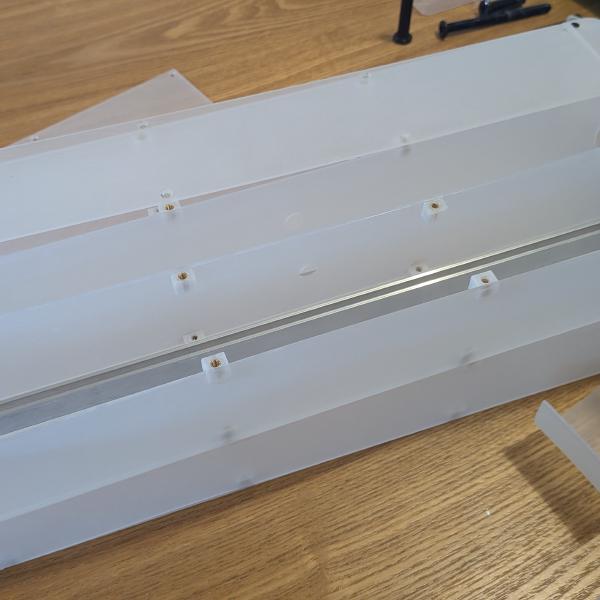
I cut my LED strips to length, and glued each one on an aluminium strip. I soldered white wires on both ends (as short as possible to avoid dangling wires 🤞). For the back top segment, I had to drill a hole into the aluminium and cut the LED to make space for the bolt to lock the lamp in place.
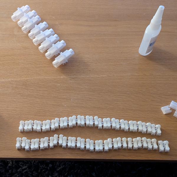
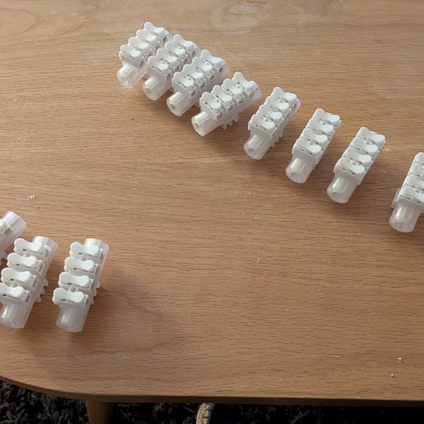
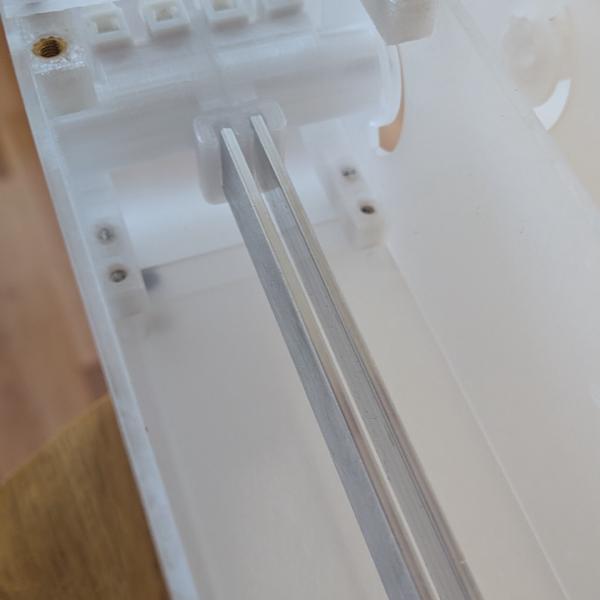
Then I started connecting the LEDs. This step was the most tedious because the wires were just long enough. I used tweezers to pass them through the arc-shaped hole between segments, and connected them to the connectors, which required pushing on them to open them. All this inside a tiny space, requiring unscrewing 16 screws at minimum to connect 2 segments. And there are 8 of these… And it was time to see the thing glow.
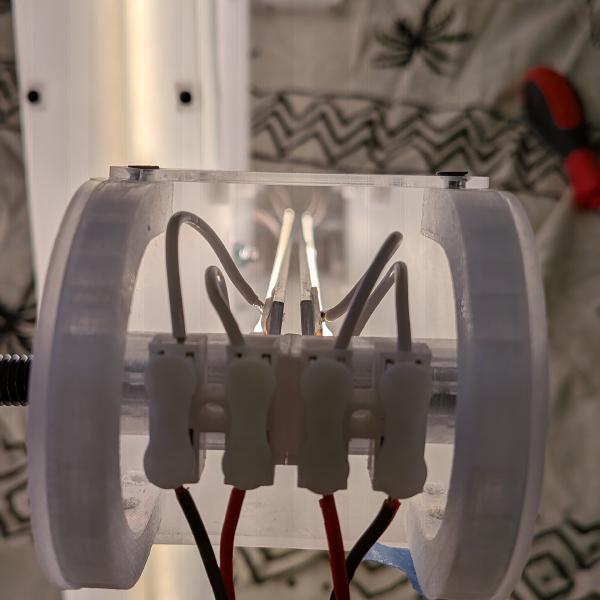
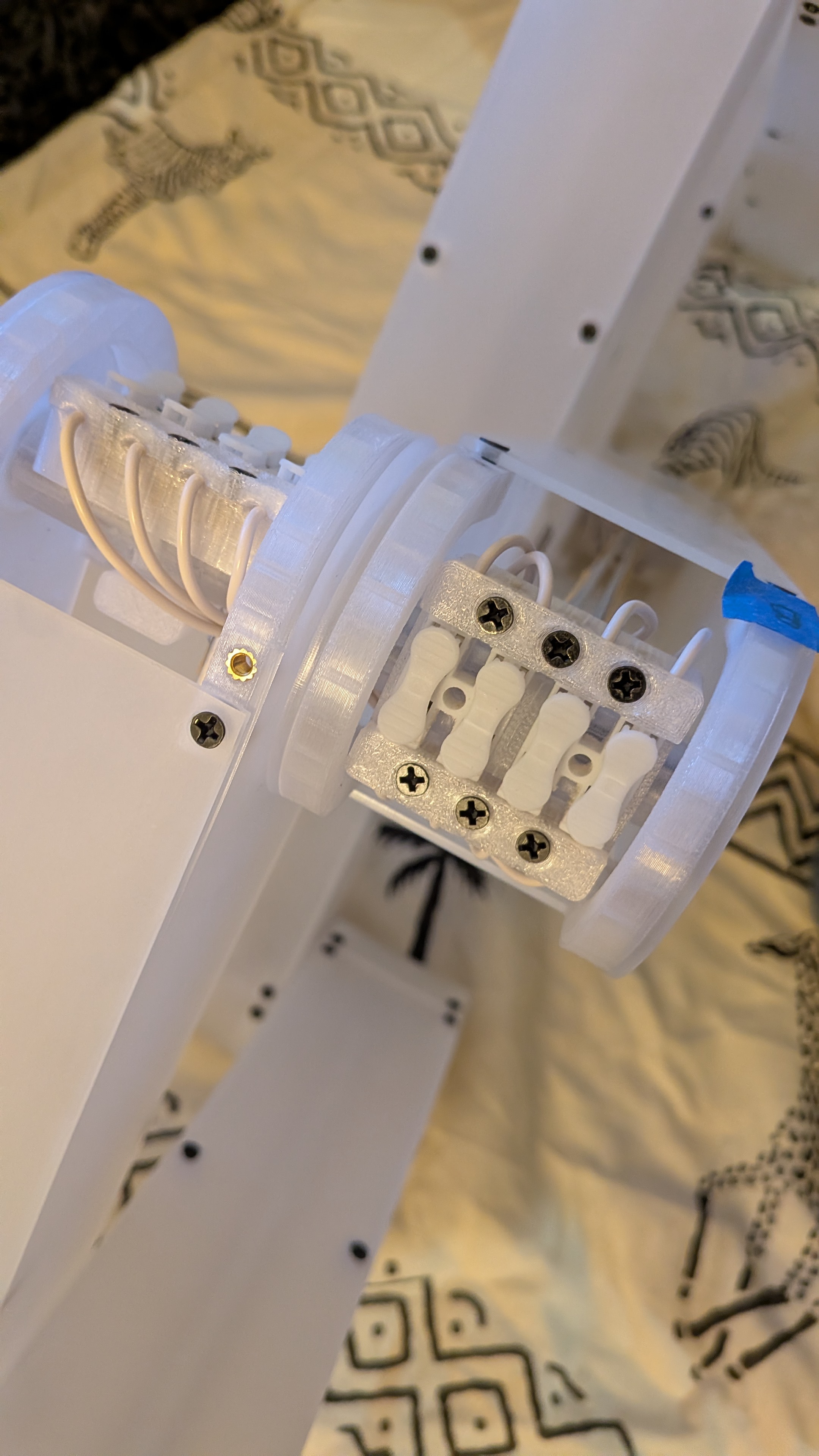
Right after that I started seeing false contacts when I tried to move the lamp. The wires I cut and soldered onto the LEDs were a bit short as I feared, and the push-to-release connectors I used were not really holding the wires very firmly. So, I needed to find a way to fix that more securely after soldering longer wires. I designed a sort of clamp, mounted on the existing pivot with a press fit.
This means one thing: a few more threaded inserts to install and each connection to be re-made.
Dimming the lamp
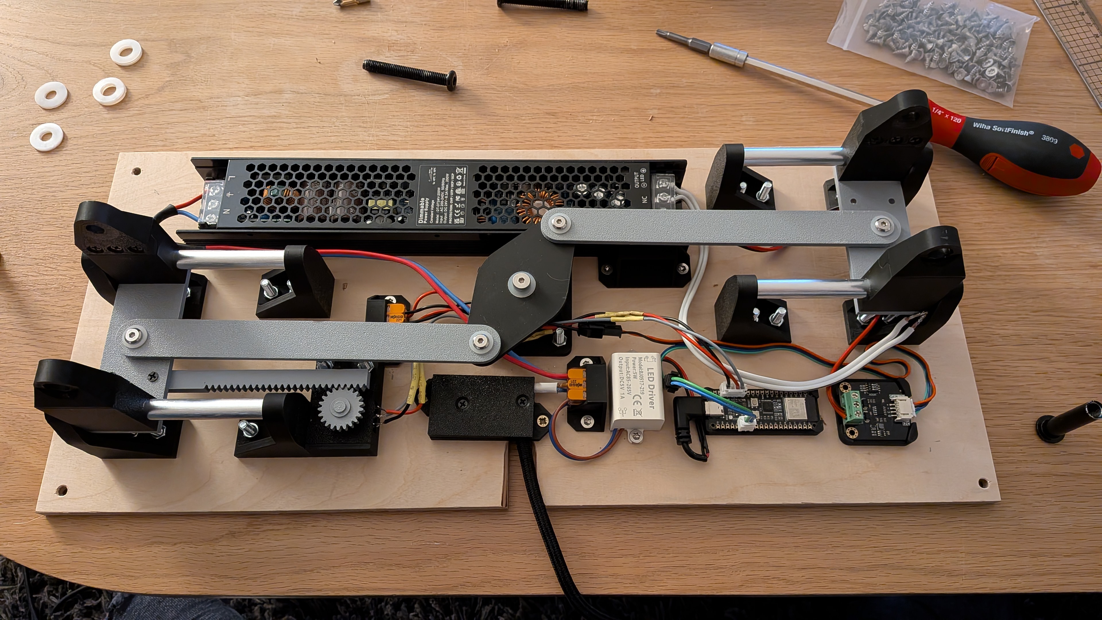
Then comes my last improvement. I loved the intensity based on the height of the lamp, it’s a nice showoff. But let’s be honest, the lamp is way nicer when fully extended. So being able to extend it to the top and set the intensity as I want should be great. For that I can’t use only a potentiometer directly connected to the power. I need to combine the potentiometer with a controller (an ESP32 C6). The controller will compute the intensity based on the position of the lamp, or as received from the remote. I used a 24V dimmable power source, controllable through a 0-10V input. I placed a DAC module (GP8403 2-Channel I2C 0-10V DAC Module) between the controller (3.3v) and the power supply.
Using Claude I computed the rack and pinion teeth parameters to make the 300° of rotation of my potentiometer correspond to 55mm of travel on the base.
Two prints later, I finally tested everything, except the remote.

Concrete base
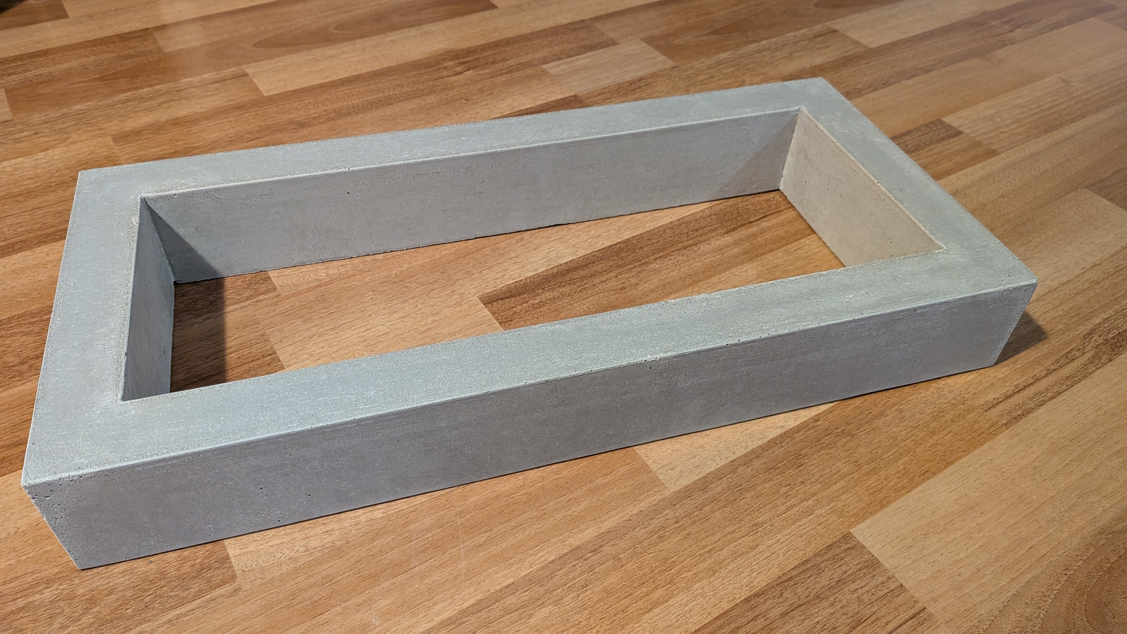
Now that I have a working lamp, the concrete base makes so much sense. Raising the lamp takes a bit of strength and the base needs to be quite heavy to stay in place. So I designed the smallest possible concrete base to host the sliders, the power supply and the electronics. I was hoping to have a smooth concrete, and remembered viewing a Modustrial Maker video, mentioning a specialized concrete exactly for this, GFRC. The first step to get there was the form, made from a sheet of melamine.


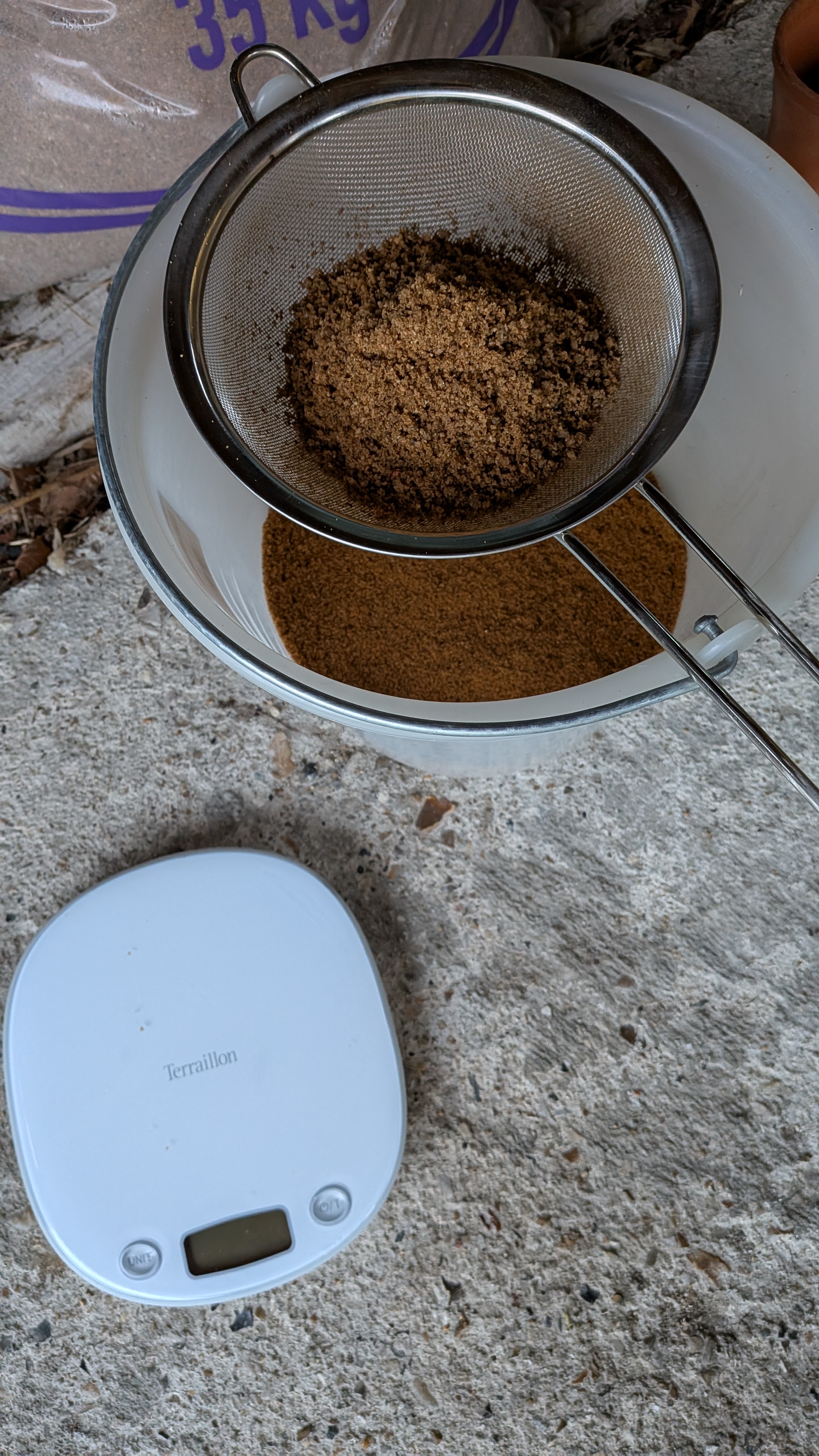
I bought a GFRC kit that came with a calculator for all the ingredients; it was quite easy to make the concrete. I opted for white concrete and added some black colorant into the mix, and, following a test, I sifted the sand to remove the big grains, hoping it would reduce the orange/yellow tint it had in the concrete.
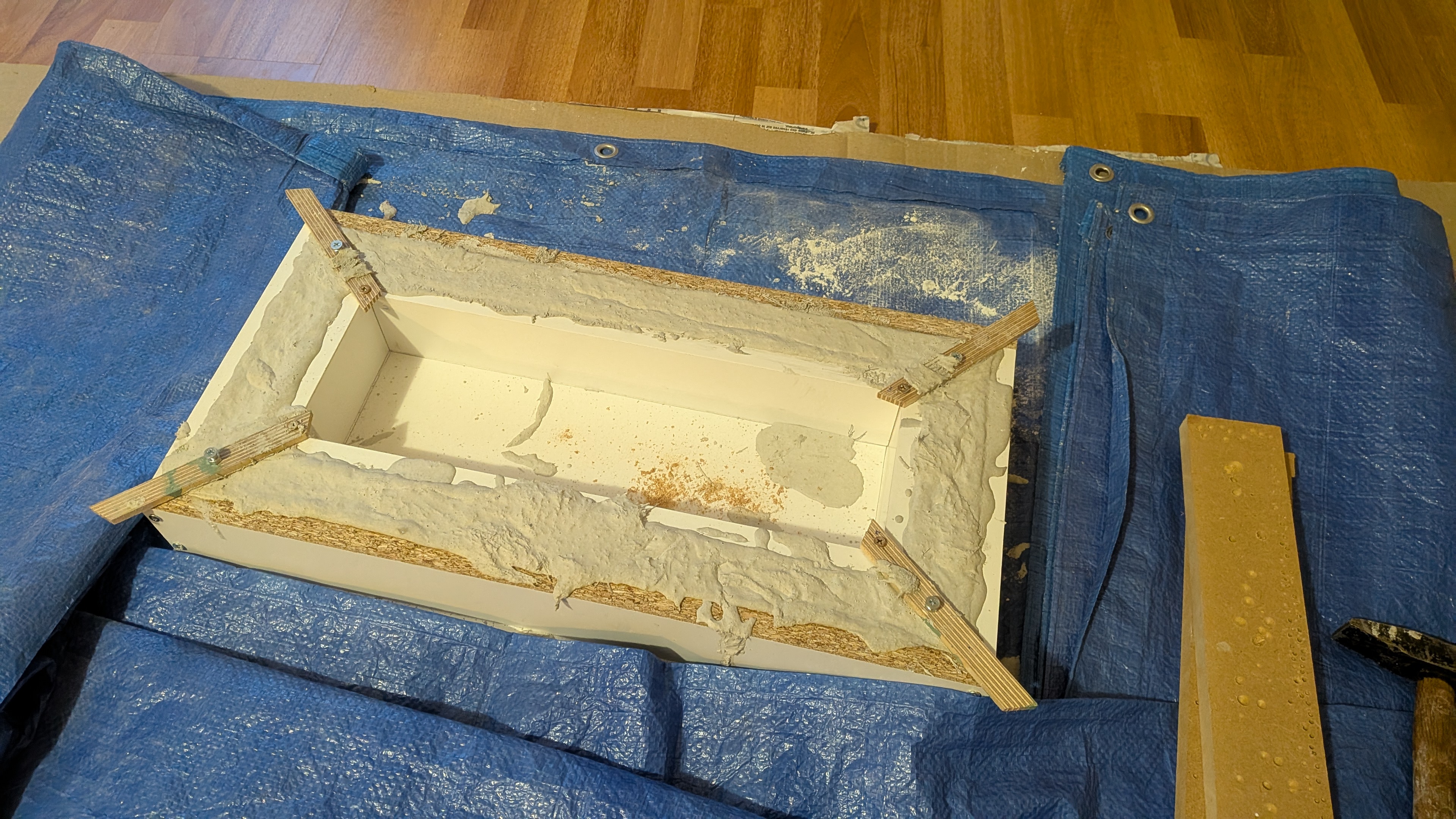
During the concrete pour, I embedded M6 threaded inserts in each corner of the concrete, allowing me to screw a plywood sheet under the base. I just routed a groove inside the sheet to allow the electric cord to pass under the base. And then I screwed all the electronics onto that plywood sheet.
The remote
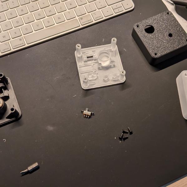
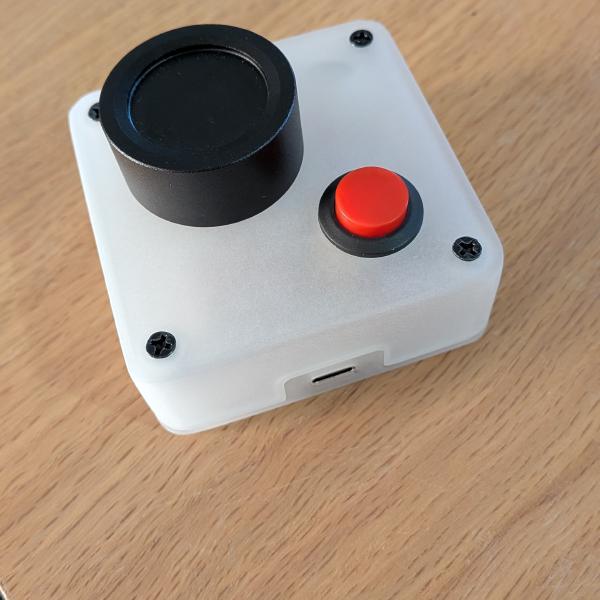
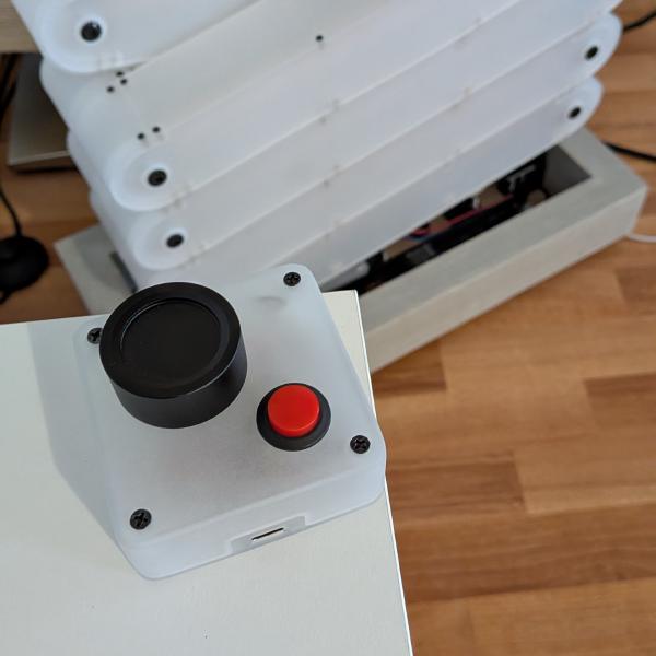
I wanted to have the simplest remote for two reasons: the first being that I would have to build it, and the second being that I wanted the easiest possible use. The idea of having only a knob to turn was nice but I was wondering how to handle the controller and its battery consumption, requiring it to constantly read the potentiometer for changes. A power switch could fix this, but switching on a remote before using it feels a bit tedious. Then I discovered “momentary buttons”. They are switches that are on when pressed, and off when released. So the remote will have a knob to adjust the brightness of the lamp, and a momentary switch to power it on and off. Great. I designed the remote with the same textures as the lamp: blurry transparency, with the black Phillips screws clearly visible.

This is the final design, but fitting the battery, the ESP32 C6, the potentiometer, the momentary button, and one extra switch on the bottom was not easy. Here are all the prototypes I printed to validate each step:

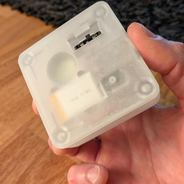
Why an extra switch, you might ask? I planned to recharge the battery through the ESP32 USB-C port, but because the momentary switch was between the battery and the controller, the circuit was open, meaning I would have to press that button for 45 minutes to recharge the battery. So I added a parallel circuit between the battery and the controller, controlled by an on/off switch. So when I want to charge the remote, I switch it on from the bottom and connect it to the front USB-C port. Achieving this blurry transparency with an FDM printer is not really doable, so I ordered a resin print of the case, and sanded it to match the lamp aesthetics. The result was better than what I could have expected.
Conclusion
This was the best build I’ve achieved to date. Doing this during the free time I had, and thinking about the problems to solve when I wasn’t, was really great. And I had many problems, countless wrong solutions, and a few good ones. Thanks to Robert’s great idea and execution, I knew this was possible. I’m not sure I would have tried something like this on my own. There are so many things I haven’t described here, like the top lock mechanism to hold the lamp in place, the software, the remote layout, etc. Maybe I will add another post for that.